This paper provides a short summary of the upcoming Future Energy Exports Cooperative Research Centre (FEnEx CRC) and points of alignment with the OIIE.
Release Date: Tuesday, 28 April 2020
Whitepaper:
Open Standards for Physical Asset Management
This paper provides a short summary of the upcoming Future Energy Exports Cooperative Research Centre (FEnEx CRC) and points of alignment with the OIIE.
This paper provides a short summary of points of alignment between National Energy Resources Australia (NERA)objectives and the OIIE with a focus on NERA knowledge priorities.
MIMOSA Announces SAP Membership to Support Interoperability Standards
November 1, 2016 – MIMOSA, which provides information standards for physical asset management, announced today that SAP has joined the organization to incorporate MIMOSA’s industry standards on SAP® Asset Intelligence Network. Alan Johnston, president of MIMOSA said, “I am very pleased to have SAP join MIMOSA and support the Open Industrial Interoperability Ecosystem. This way, we expect that many more of the owner/operators in asset-intensive industry groups will gain business value from SAP Asset Intelligence Network running on the new SAP HANA Cloud Platform when they leverage our open standards.”
MIMOSA provides a broadly used portfolio of industry standards for physical asset management and leads the development of the Open Industrial Interoperability Ecosystem (OIIE), in cooperation with other industry standards associations. Ken Dunn from BP, who is chairman of the MIMOSA board, explained: “The OIIE incorporates a portfolio of international and industry standards which enable sustainable standards-based interoperability. It is designed to dramatically reduce the cost of integration across a heterogeneous information technology environment and to facilitate the Industrial Internet of Things (IIOT). The OIIE is even more important in economically challenging times, as it helps owner/operators reduce cost and complexity, while continuing to sustain critical programs around asset integrity management and operational risk management. SAP’s commitment to these industry standards is a major step forward in their widespread adoption.”
SAP Asset Intelligence Network will provide a global registry of industrial equipment designed to enable collaborative business models. Achim Krueger, VP of Global Solutions for the SAP Extended Supply Chain (which includes Asset Management and HSE), commented, “Being part of this interoperability standards organization will become a key support of SAP Asset Intelligence Network, benefitting our entire ecosystem of manufacturers, engineering suppliers and asset operators. The intent is to enable them to automatically exchange their asset management data and reduce manual steps in the process. This is a great example of how SAP continues to work with the industry to co-innovate new solutions that are important for our customers.”
Ken Evans, head of SAP Global O&G Business Unit, stated, “As our customers digitally transform their global operations, they need greater flexibility in their business and operations technology platforms. We view joining MIMOSA as an important step to support their ability to openly integrate SAP Asset Intelligence Network with their ecosystem of service providers. We are excited to continue our innovations with the O&G industry and to utilize standards to improve overall enterprise process efficiency and access to operational content.”
###
SAP, SAP HANA and other SAP products and services mentioned herein as well as their respective logos are trademarks or registered trademarks of SAP SE in Germany and other countries. Please see https://www.sap.com/corporate/en/legal/copyright.html for additional trademark information and notices.
SAP Forward-looking Statement
Any statements contained in this document that are not historical facts are forward-looking statements as defined in the U.S. Private Securities Litigation Reform Act of 1995. Words such as “anticipate,” “believe,” “estimate,” “expect,” “forecast,” “intend,” “may,” “plan,” “project,” “predict,” “should” and “will” and similar expressions as they relate to SAP are intended to identify such forward-looking statements. SAP undertakes no obligation to publicly update or revise any forward-looking statements. All forward-looking statements are subject to various risks and uncertainties that could cause actual results to differ materially from expectations. The factors that could affect SAP’s future financial results are discussed more fully in SAP’s filings with the U.S. Securities and Exchange Commission (“SEC”), including SAP’s most recent Annual Report on Form 20-F filed with the SEC. Readers are cautioned not to place undue reliance on these forward-looking statements, which speak only as of their dates.
MIMOSA Information
MIMOSA is a 501 (c) 6 not-for-profit industry association which develops and publishes open, supplier-neutral industrial standards for asset intensive industries. Further information about MIMOSA can be found on its website at www.mimosa.org.
Contact:
Alan Johnston
gro.a1785674301somim1785674301@nhoj1785674301ta1785674301
2200 Jack Warner Pkwy
Suite 300
Tuscaloosa, AL 35406
Over the past year, a few software vendors have expressed interest to MIMOSA in exploring an alternate web service technology stack based on REST and JSON rather than traditional SOAP and XML that we typically find used in Enterprise Application Integration. This is somewhat due to the perception, particularly driven from the open-source web application development community, that SOAP and XML carry a lot of overhead and baggage. In this article, I’ll compare the incumbent approach based on SOAP, which MIMOSA uses with the OSA-EAI, OSA-CBM and more recently, the OpenO&M Web Service Information Service Bus Model (ws-ISBM) to one based on REST. I’ll also discuss what the implications are of adding a RESTful stack may have on the work that we are doing with the OIIE (Open Industrial Interoperability Ecosystem).
SOAP (Simple Object Access Protocol) was developed as an object-access protocol in 1998 with the latest version, SOAP 1.2, released in 2003. It is based on HTTP and XML as underlying standards and is often used in combination with Web Services Description Language (WSDL) for specifying Web Services.
REST (Representational State Transfer) is an architectural style that was developed in 1996 in conjunction with HTTP 1.1. It usually involves operating a verb (e.g. GET, POST, DELETE) on one-to-many resources identified by a URL. There is no official standard for RESTful web APIs as it describes an approach rather than a protocol; however, most RESTful implementations are based HTTP, JSON and XML.
While MIMOSA does not have an official framework on which it bases its technology adoption, we generally evaluate the follow characteristics before adopting different technologies into our standards portfolio:
I’ll use these characteristics as the basis of analyzing SOAP and RESTful approaches in the following sections.
While it is only a handful of organizations that have expressed interest in exploring a RESTful stack, these have exclusively been software vendors rather than end users. It is not unsurprising that end users show little interest in specifying technological requirements, as their focus is on supporting the line of business and its requirements. If a particular technology assists in supporting business requirements in a more effective and efficient manner, then there would be a strong value proposition for technological change. If it is change for its own sake, then this becomes a less compelling reason since legacy systems using older technologies still require support (it is uncommon to see a major uplift on brownfield sites).
Software vendors on the other hand, are intrinsically tied to technological progression, and from experience, software developers like new and shiny things. From a business perspective, vendors derive revenue through sales and support contracts – new products and features means additional revenue streams. Concurrently, older or neglected technologies also mean increased support costs to vendors with a diminishing talent pool.
From the software vendors, only one is a current MIMOSA member, while the others are in the process of becoming members. Like end users, existing vendor members have investment tied up in supporting existing implementations, while new entrants can be more agile with a blank slate.
The current work priority for the MIMOSA Technical Committee is to support the OIIE and associated standards. The place within the OIIE where a RESTful approach applies is in the spot where the OpenO&M ws-ISBM is positioned. The ws-ISBM provides a standard interface based on SOAP web services that facilitates the exchange of data between applications.
The purpose of the OpenO&M ws-ISBM (and the abstract model that was extracted to ISA 95 Part 6 Message Service Model) is to provide a fixed set of web services using common messaging patterns supporting an unlimited number of message types. The ISBM would eliminate each standards organization from having to specify a data transport standard to be used with their data exchange standards, and therefore allow the standards organization to focus on the data content. This would then give software vendors some comfort to support a limited set of web services natively within their applications, and software vendors could implement support for messages that corresponded to relevant data exchange use cases and scenarios. SOAP was naturally chosen as an implementation specification, since the vast majority of standards-based integration uses SOAP if not XML.
That said, a RESTful approach can be applied to the ISBM and was in fact, envisioned by the editors of the ISBM and MSM specifications. An example proposal of a RESTful ISBM is shown in the appendix using a direct translation of the concepts from SOAP. There are, however, some non-trivial issues that the OpenO&M Technical Committee would need to address:
Expanding on the first point, at present, all of the data specifications specified by the OIIE Use Cases and Scenarios are XML-based or have XML representations. OAGi (Open Applications Group), one of the OpenO&M Imitative members, more recently published a JSON representation in addition to their XML representation for their data specifications, presumably to support demand by their members. While the ws-ISBM based on SOAP can technically support JSON message structures by embedding the JSON in the SOAP Body, the ws-ISBM would require a minor additional specification to do so in an interoperable manner.
Thus the primary functional driver for developing a RESTful implementation of the ISBM specification will be the support for non-XML messages formats.
While technologically REST/JSON appears as a superior alternative to SOAP, where it falls down is at a standards level. Most RESTful services offered by organizations will follow conventions, but there isn’t a well-adopted standard that can be followed. Initiatives like JSON API are trying to fill that gap, but these are currently immature, and having organically grown to fulfill a need, currently aren’t part of the W3C or IETF. JSON Schema, published by the IETF, is still a draft standard. RDF/JSON, published by the W3C, is still a draft standard. And then there are no well-adopted, standardized, drop-in replacements for WS-Security, WS-AtomicTransaction, WS-ReliableMessaging.
The fact that organizations are expressing interest in supporting RESTful interactions clearly indicates that there is a need for us as a standards organization to be watchful in this space. We can also see from a Google Trends comparison between the terms “web service soap” and “web service rest” that there is an inflexion point during 2014-2015 where the searches made on Google are starting to favor REST:
This inflexion point is hit in 2013 if the search terms “soap xml” and “rest json” are compared:
The two dominant enterprise application development frameworks of Java and .NET have long supported SOAP Web Services including contract-first code generation from WSDL. Microsoft added support for JSON serialization in .NET 3.5 (released in 2007) while Oracle added JSON support to Java EE 7 (released in 2013). Particularly in the case of Java, third-party libraries seem to be preferred compared to using the core libraries, and hence the late arrival into the Java core libraries.
It should be noted that due to the asset-intensive industries that we work in where legacy systems can mean working with information technologies 10-20 years old (if not older), we often do not have the luxury to use modern technology stacks if we need to support brownfield sites. The case for greenfield sites is usually different, but is influenced and restricted by the requirements of brownfield sites against the corporate strategic technology roadmap.
The use of SOAP web services is closely tied with the use of WSDL, which provides metadata about a service and allows software developers to generate code, dealing with higher level data transfer objects, rather than lower level constructs. While WADL (Web Application Description Language) was proposed as a WSDL equivalent for REST web services, it has not been standardized by the W3C. Initiatives such as Swagger will automatically document metadata and even perform client code generation, and while open-source, it is not based on a published industry standard.
As software developers need to implement code to facilitate the exchange of data, let’s have a look at the differences in complexity to generate and consume the SOAP and REST HTTP payloads shown above. I’ll use Ruby for the examples, as one of its tenets is to optimize for developer happiness (and therefore simplicity and readability). Like Java and .NET, it contains libraries to help with heavy lifting.
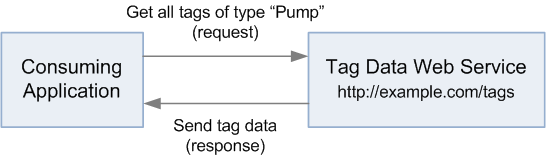
I’ll use a very simple scenario of an application requesting tag data for pumps from another application hosting a tag data web service. While it doesn’t use an intermediate ISBM Service Provider, it is still illustrative of the comparison.
To generate the SOAP HTTP request and output the response:
tag_type = "pump"
require "savon"
client = Savon.client(wsdl: "http://example.com/tags?wsdl")
response = client.call(:get_tags, message: {"Type" => tag_type })
puts response.body
To generate the REST HTTP request and output the response:
tag_type = "pump"
require "httparty"
response = HTTParty.get("http://example.com/tags?type=#{tag_type}")
puts response
While this example is simplistic as it is hardcoded to a “Pump” type, it illustrates that there is little difference in code complexity between a SOAP and RESTful approach. The majority of work when developing data exchange adapters is in marshalling and unmarshalling data from and to an application data model rather than building the request or receiving the response.
REST/JSON is generally touted as a more performant solution than SOAP and others have conducted studies that confirm the assertion, particularly when dealing with less powerful devices such as mobile devices. This is primarily due to the complexities in parsing XML vs JSON rather than the HTTP call itself – XML and particular XML Schema, is a more complex specification than JSON, with the complexity allowing for greater functionality. This complexity, when implemented in parsing libraries, will result in slower performance, and tangentially, increase the maintenance cost of those libraries.
Transport layer communications with both SOAP and REST takes place using HTTP (Hypertext Transfer Protocol) using a request and response model. Using the scenario above of requesting tag data, we can put together some examples of what this might look like when it gets to the HTTP layer.
Here is an example HTTP request that would be sent in a SOAP exchange:
POST /tags HTTP/1.1
Content-Type: application/soap+xml; charset=utf-8
Content-Length: 128

<s:Envelope s:xmlns="http://www.w3.org/2003/05/soap-envelope">
  <s:Body>
    <GetTags>
      <Type>Pump</Type>
    </GetTags>
  </s:Body>
</s:Envelope>
Here is an example HTTP request that would be sent in a REST exchange:
GET /tags?type=Pump HTTP/1.1
The RESTful approach is considerably smaller than the SOAP approach and for this particular example, while the SOAP request can be cut down to 219 bytes, the RESTful approach is 28 bytes. Apart from the size, there are several differences:
| SOAP | REST | |
|---|---|---|
| HTTP Method | SOAP only uses the POST HTTP method. | REST uses the entire vocabulary of HTTP methods. In this case, since the application is querying information related to a tag, the GET method is the most appropriate since it is used for retrieving information. |
| Request Data | The request data for a SOAP message is placed within the SOAP Envelope’s <body> XML tag. A SOAP Envelope also allows the use of a <header> XML tag for additional functionality, which can be omitted if unused (as with this example). |
A GET request contains no body, and therefore all data must be included in the URL as a query string. |
Here is an example HTTP response that would be sent in a SOAP exchange:
HTTP/1.1 200 OK
Content-Type: application/soap+xml; charset=utf-8
Content-Length: 290

<s:Envelope xmlns:s="http://schemas.xmlsoap.org/soap/envelope/">
  <s:Body>
    <GetTagsResponse>
      <Tag>
        <Id>0f8d4ced-8b4e-46da-9a6b-db7d68f35aa1</Id>
        <Name>P-11001</Name>
        <Type>Pump</Type>
      </Tag>
    </GetTagsResponse>
  </s:Body>
</s:Envelope>
Here is an example HTTP response that would be sent in a REST/XML exchange:
HTTP/1.1 200 OK
Content-Type: application/xml; charset=utf-8
Content-Length: 134

<Tags>
  <Tag>
    <Id>0f8d4ced-8b4e-46da-9a6b-db7d68f35aa1</Id>
    <Name>P-11001</Name>
    <Type>Pump</Type>
  </Tag>
</Tags>
Here is an example HTTP response that would be sent in a REST/JSON exchange:
HTTP/1.1 200 OK
Content-Type: application/json; charset=utf-8
Content-Length: 117

{
  "tags": {
    "id": "0f8d4ced-8b4e-46da-9a6b-db7d68f35aa1",
    "name": "P-11001",
    "type": "Pump"
  }
}
Similar to the HTTP request, the SOAP HTTP response is larger at 313 bytes, compared to 171 bytes for the REST/JSON HTTP response and 192 bytes for the REST/XML HTTP response.
Again, there is a lot of ceremony that is included with the SOAP Envelope structure leading to the larger size. Another difference can be seen between JSON vs XML in that the object type in the JSON tags array is implied by the serializer/deserialzer on either side of the exchange, while the XML examples make the <Tag> node explicit.
While a JSON approach will always result in smaller payload sizes than XML, I wanted to explore the difference with a larger example, where the overhead of the SOAP Envelope would become relatively inconsequential. Using the MIMOSA CCOM (Common Conceptual Object Model) representation of a Debutanizer Fractionator P&ID (Piping and Instrumentation Diagram) from the OGI (Oil and Gas Interoperability) Pilot, we see the following payload sizes:
| Approach | Uncompressed (bytes) |
Gzip compressed (bytes) |
Uncompressed (% difference from REST/JSON) |
Gzip compressed (% difference from REST/JSON) |
|---|---|---|---|---|
| SOAP | 576,753 | 70,450 | 36.93 | 3.50 |
| REST/XML | 576,656 | 70,378 | 36.91 | 3.39 |
| REST/JSON | 421,188 | 68,069 | 0 | 0 |
I have included gzip compressed payload sizes, as most modern technology stacks support this as an option. I have also included the percentage difference from the smallest payload (REST/JSON).
We see that there is little difference between either the SOAP and REST/XML approaches, confirming that the SOAP Envelope adds next to no overhead on larger sized messages. However, there is a 37% difference between XML and JSON approaches appears quite significant. For a large capital project with 300 P&IDs, this difference amounts to an additional 47 MB. This is not a bewildering amount given today’s technology, and considering that gzip compression reduces this to less 1 MB, there is minimal advantage in using a JSON approach for reducing payload sizes.
So a RESTful approach looks good from a technology perspective compared to SOAP: it allows the transfer of smaller payloads over the wire, provides a (marginally) simpler programming model, and performs significantly better on lower-powered, typically mobile devices – which is a hot area of opportunity with the current Internet of Things movement. Where it significantly falls down is at the standardization level, and with MIMOSA being a proponent for standardization, our preference for technology standards is to wait until final standards are published and look like they will have broad adoption by industry.
However, the proposition is not an either-or scenario, and both SOAP and REST can potentially be used simultaneously. Similar to how SOAP 1.1 and SOAP 1.2 endpoints can co-exist simultaneously from the one service, it is conceivable that both SOAP and RESTful endpoints can co-exist in a single ISBM Service Provider implementation. Thus applications that prefer a RESTful approach can use the REST interface, while applications that prefer a SOAP approach can use the ws-ISBM interface.
To support the concurrent use of SOAP and RESTful approaches with the ISBM issues such as message formats and security tokens will need to be resolved when interchanging between the two approaches. There will also need to be some level of specification in the scenario where a message is posted using REST/JSON interface and how it is made available to subscribers using a SOAP/XML interface.
Like we have done in the past with the adoption of DTDs then XML Schema and UUIDs, MIMOSA is always open to adding different technologies in our standards portfolio, but at a time when they make sense.
As we saw in the initial description about REST, a RESTful approach will apply methods to resources. The resources associated with the ISBM are:
If we take the Channel Management Service operations and convert this to a RESTful approach, the following table shows one potential approach:
| ISBM Channel Management Service Operation | Current behavior | RESTful implications |
|---|---|---|
| Create Channel | HTTP method: POST
URL: /ChannelManagement Data: Specified in HTTP body |
HTTP method: POST
URL: /channels Data: Specified in HTTP body |
| Add Security Tokens | HTTP method: POST
URL: /ChannelManagement Data: Specified in HTTP body |
HTTP method: POST
URL is /channels/{channel-id}/security-tokens Token data is specified in HTTP body |
| Remove Security Tokens | HTTP method: POST
URL: /ChannelManagement Data: Specified in HTTP body |
HTTP method: DELETE
URL is /channels/{channel-id}/security-tokens/{token-id} Data: Specified in URL |
| Delete Channel | HTTP method: POST
URL: /ChannelManagement Data: Specified in HTTP body |
HTTP method: DELETE
URL: /channels/{channel-id} Data: Specified in URL |
| Get Channel | HTTP method: POST
URL: /ChannelManagement Data: Specified in HTTP body |
HTTP method: GET
URL is /channels/{channel-id} Data: Specified in URL |
| Get Channels | HTTP method: POST
URL: /ChannelManagement Data: N/A |
HTTP method: GET
URL: /channels Data: N/A |
This conversion is based on the rules:
token-id can be passed in the URL or in the HTTP body.Engineering design parameters are a key information class usually specified for each instrument and each item of process equipment in an engineering design application. These applications reference a very complete template for each tagged item based on ASME, API, or ISA standards. Most engineering design applications have a very complete set of templates covering most of the OEM equipment required to construct the majority of chemical, refining, or oil and gas processes with the exception of custom equipment like hydrocrackers or fluidized bed reactors, or fixed bed reactors. These devices are usually patent protected and their design parameters are not generally published. Engineering design data for these devices will have to be accessed through non-disclosure agreements by each owner operator to secure these items parameters for placeholders in an O&M Repository.
Securing the largely available public engineering design templates for as many common equipment classes as possible and using them as data element place holders secures an interoperable context for receiving information from engineering design applications. This is the primary goal for completing the near term work for this class of information. To illustrate the engineering design data concept consider the following figure that shows a snippet of the total categories and associated parameters from the ASME B73.1 – 2001: Specification for Horizontal End Suction Centrifugal Pumps for Chemical Process.
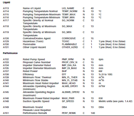
Even for these two limited categories, the parameters allow for the specification of this type of equipment without specifying a particular vendor and OEM Model number. The specification supplies general performance curves for these to specify desired efficiency, impeller size, etc. so the general operating range of the pump and its ability to handle the required fluids going through it can be specified without resorting to a vendor catalogue search. The design specification is very complete to enable an engineer to specify almost any pump requirements for pumps of this type, and there are appropriate data place holders for the range of equipment without inventing new parameters. By using this specification format for engineering design parameters organized into a category and attribute template for storage in the O&M Repository for pumps of this type, you would have a high probability of having a deterministic data format to place design information with confidence that you will not have a piece of information come to you that cannot fit in the template. In fact, this is exactly what engineering design system vendors do to cover a very high percentage of their equipment specifications with most of the templates being based on existing standards (ASME, API, ISA, etc.) covering thousands of equipment types – pumps, heat exchangers, vessels, pipe segments, pressure parts, distillation columns, instrument measurement elements, instrument loop components (e.g. controllers, transmitters, etc.). Also these templates can be exported in XML format, or at the very least, exported in some organized file format.
In the near term, work in the OGI Pilot will involve gathering templates from the engineering design vendors for all equipment and instrument types, comparing them and ensuring that these types and parameters are covered in the ISO 15926 Reference Data Library (RDL) and grouped in a similar fashion. If they are not present, they are to be submitted to PCA to ensure that the RDL contains a superset of design specification parameters and templates that are useful, documented, and acceptable by all parties.
Two important engineering drawings and knowledge transfer constructs are Process Flow Diagrams (PFD) and Piping and Instrumentation Diagrams (P&ID). These drawings contain visual information and important metadata information about the logical location of a process area and equipment usually organized in a hierarchy defined by an engineering design system. Ideally, the engineering design system’s plant location hierarchy can be mapped to the ISA 95/ISA 88 hierarchy site area, Work Center or Process center functional location, and segment breakdown for equipment. Doing this provides more flexibility and enables a more granular organization and access for information. PFDs and P&IDs are the primary means to convey how the different process areas of a refinery or chemical process work and relate to each other. P&ID drawings are an extremely important visual training and diagnostic aid to engineers and operators. Unfortunately, contrary to its importance, P&ID information is rarely passed in a consumable, electronic manner as a staged means to organize information loads for operational systems or as repeatable visually rendered means for bringing clarity in the operational and maintenance field to personnel. P&IDs are a critical training and reference tool.
The most important information conveyed by PFDs and P&IDs are the equipment connection relationships, requiring support for:
The second most important information conveyed by PFDs and P&IDs are the graphical representations of process equipment and instrumentation equipment along with key parameters and information available for each process equipment item. This provides a very rich set of provenance for the equipment item that is directly used to characterize the following:
Traditionally engineering applications systems have never transferred PFD and P&ID information other than as human readable documents in viewing formats like PDF. Basically these are set piece documents that in themselves do not yield any value for engineering data handover. Export of data has been largely a proprietary export of reference data elements organized as the author of the export interface designed.
Recently, significant progress has been made leveraging the ISO 15926 standards effort to output them via XML, RDF, or OWL-based electronic encoding. One of these mechanisms is the result of the PCA/Fiatech Proteus Project. The Proteus project was formed to provide ISO 15926 data exchange of intelligent P&ID data between vendor engineering design systems, exchange of data between different vendors, 2D P&IDs and 3D models. This was a significant step to accomplish the challenge of engineering data transfer for a large subset of the P&ID information required to bootstrap or initially load operational and maintenance systems. However, additional specification work must be added to this export method to accomplish the transfer of the full set of engineering data needed to provide all services for the operations and maintenance environment to provision/configure applications and for management of change. The goal is to identify a method to populate a common interoperable register and O&M engineering data repository using a small set of methods for all engineering design applications.
Digital plant information is now seen as valuable an asset as the physical plant itself. Accurate capital project information handover is vital to enterprise profitability. Following handover, plant information must be kept accurate and accessible for the lifetime of the facility, which typically spans 30-50 years. Inaccurate or missing plant information causes lost revenue due to missed project deadlines, unnecessary material purchases, design rework, start-up delays, production cutbacks, and unplanned shutdowns. This business use case focuses on the periodic information handovers of information from capital project systems for use in plant operations and maintenance (O&M) systems. This handover activity is vital to bringing a new plant on line within time and budget as it drives the compilation and validation of the records necessary to pass into and support the operational life of the plant, together with their transfer of ownership from the project team and acceptance by the plant owner.
Essential to quickly bringing a plant into production and enabling plant O&M personnel to safely operate the plant, is populating O&M systems with essential information about the as-designed engineering structure of a plant with the required operating parameters, the as-procured product data, and the as-built serialized assets. The specific information needs of O/O, EPC, and OEM personnel are quite different. The O/O is concerned about the long-term needs for the life of the facility, the EPC focuses on the capital project design and construction phase, and the OEM is concerned with the requirements and delivery of products which they either Make-to-Stock or Make-to-Order.
Studies by FIATECH, estimate that the traditional execution by an EPC of handover is typically quantified as less than 0.3% of the project, but that a further 2-4% of the project cost is required by the O/O to manually correct and key in required O&M information into O&M systems. This means that handover traditionally only equates to $1M on a $400M project for the EPC, but the O/O then has to spend an additional $8-16M in “hidden” data entry and validation costs. Fiatech studies have shown that periodic, structured, non-proprietary, automated information exchanges from EPC systems to O&M systems are estimated to save 60% of this O/O hidden cost, resulting in a savings of between $5-10M on a $400 million project. To maximize these savings, there are four major problems which must be addressed.
The first barrier to overcome is the big bang approach to information handover from the EPC to O&M personnel. O/Os often experience unexpected delays in startup if information is not periodically assembled, delivered, and reviewed during the project. Often, capital projects wait until startup/handover to dump the design and information to O&M personnel to populate their systems. Since this occurs at the end of the project, cost pressures can be extreme due to earlier problems. As a result, it can be tempting to cut handover spending to hit the project budget. It is not uncommon for an O&M organization to have the burden of finding and validating data to populate their systems after startup.
Recommendation Both EPCs and O/Os should follow the periodic, phased handover methodology captured in NIST’s Capital Facilities Information Handover Guide (CFIHG) to improve the efficiency and quality of information handovers throughout the capital facility life-cycle. The CFIHG provides a framework for the definition and delivery of information packages to be transferred among participants in capital facility projects. Information handover strategies shall be based on identifying the information created in each phase that will be needed downstream and how it will need to be used. It is essential that the facility life-cycle information strategy and the handover requirements be established before project initiation so that contractual requirements for a continuous information handover can be defined.
The second problem is the use of unstructured data exchange formats for information transfer from engineering to O&M personnel. Traditionally, most plant engineering information is available to O&M solely in unstructured document-oriented formats that cannot be readily machine-interpreted. Examples of these unstructured formats include PDF, JPEG, TIF, Microsoft Excel and Microsoft Word. While these formats have value for the human reader, they are of limited value to populate O&M systems since it is difficult for computer software to extract information such as the tag identifier from a P&ID diagram represented in a PDF format. Since manual data entry from these unstructured documents is now required, data integrity problems are common between engineering and O&M systems, which can result in operating mistakes. Another resulting problem is the existence of redundant equipment files, created by both maintenance and engineering, which are not synchronized, creating recurring engineering and maintenance errors. This can result in unplanned shutdowns, delayed maintenance projects, and incidents.
Recommendation Plant information should be generated as structured, computer-readable, and O&M-meaningful that can be linked to derivative unstructured document. Plant structural information should be generated by engineering systems from logical P&IDs and PFDs, and placed into computer system readable formats such as XML or RDF. The extracted structural information packages should be defined as specified in the CFIHG handover plan section and should include the equipment/tag identifiers with requirements such as operating envelope setpoints, I/O port connections with process flow information, as-built serialized asset data, and associated plant breakdown structures.
The third problem is the proprietary format of data exchange handover information. As specified in CFIHG, handover requirements – content description and exchange format – should be defined in the contract between EPCs and O/Os. Even though structured formats are utilized by an EPC, unless the information is originally created with knowledge of the final desired handover format, it may be difficult and expensive to convert. A study conducted by the Construction Industry Institute (CII) in the United States in the early 1990s suggested that the effort to convert facility drawings developed manually or in an unstructured CAD format to a structured model was ineffective in controlling construction costs or schedule, while the use of information-rich models during design did result in such benefits.
Recommendation Specify that outputs from EPC systems shall be formatted accordingly to ISO 15926 and OpenO&M-standardized formats using ISO 15926 and PCA/JORD Reference Data. ISO 15926 employs a generic data model that is supplemented with OpenO&M templates and a Reference Data Library (RDL) to support standardized transfers of information packages throughout the complete life cycle of a facility. Specifying only ISO 15926 and OpenO&M-standardized formats provides a standardized definition of data exchange packages for accessing and presenting model data in any way the end user requires.
To be consumed by O&M execution environment systems, the reference data transferred in OpenO&M ISO 15926 RDL templates need to be converted to the standard for registry data – the MIMOSA Common Conceptual Object Model (CCOM) XML format.
Note The Joint MIMOSA/PCA O&M Special Interest Group is working to properly incorporate MIMOSA CCOM concepts in ISO 15926 so that key O&M information can be unambiguously exchanged based on existing O&M information models.
The final problem to address is the manual data exchange methods from Engineering and Construction Systems to O&M systems. Plant engineering and construction systems that contain updated Plant Breakdown Structures, P&ID and PFD as-designed and as-built data need to periodically publish revisions to O&M onto a safe and secure information bus using a Service-Oriented Architecture (SOA) methodology and subscribe to revisions to the as-maintained state of equipment from this same information bus.
Recommendation All systems should support the OpenO&M Information Service Bus Model (ws-ISBM) SOA architecture, which can be implemented by major Enterprise Service Bus (ESB) suppliers to provide systemic notifications of information changes in a safe and secure transport with guaranteed delivery.
Recommendation Include the use of an OpenO&M-ISO 15926 Transform Engine on an ISBM, transforming ISO 15926 content received by the Active O&M Registry from Engineering to MIMOSA CCOM XML format with the use of the OpenO&M Web Service Common Interoperability Registry (ws-CIR) for index lookups and returning this data back to the Active O&M Registry system via the ws-ISBM.
Recommendation The OpenO&M best practice also includes the use of an Active O&M Registry which subscribes to the output from the Transform Engine and provides a centralized GUID registry for all O&M data dictionary items (REG-DICTIONARY), data dictionary taxonomies (REG-TAXONOMY), system structures (REG-LOCATION), serialized assets (REG-ASSET), and product templates with product models (REG-PRODUCT).
MIMOSA is a member of both the OpenO&M and the Standards Leadership Council.
© 1998 - 2026 MIMOSA. All rights reserved.