The analysis and identification process of functional requirements for developing an OIIE/ISBM adapter may leverage material such as the OIIE Use Cases, Scenarios and Events. The functional requirements and subsequent design will help indicate which sections of the ISBM specification are relevant for an application. Typical requirement and design decisions that will be encountered are:
- What role does my application play?
- Which transaction models will my application need to support?
- Which interface style (e.g., REST or SOAP) is most appropriate for my application and/or needs to be supported?
- Which channel management service methods need to be supported?
- Will my application be able to host a Web Service for asynchronous callback or will I need to revert to polling?
- What events will trigger a payload to be sent on the ISBM? What events will be triggered when a message is received?
- How will the ISBM module be configured including channel, topic and token configuration?
- How are other configuration items, such as polling or retry intervals, configured?
- How are channels and topics persisted across application restarts?
- Where will ISBM activity be logged and how are errors presented to users?
- What ISBM activity needs to be persisted for audit purposes?
The steps involved before actually implementing an OIIE/ISBM adapter are listed in this page, which includes first identifying in which Use Cases, Scenarios and Events the system needs to participate. Then, identify the underlying specific CCOM elements and perform the mappings to those CCOM elements. The relevant BODs should be identified for transferring the payloads to specific systems. An organization’s role in the OGI pilot will determine the specific interfaces of the ISBM they need to build adapter for. For example, an organization may just need to build an adaptor to consume the publications posted by another provider organization. The final part will be connecting to specific component(s) of the OIIE ecosystem via ISBM based on their requirements.
1. Identify Use Case, Scenarios and Events
The Open Industrial Interoperability Ecosystem (OIIE) is built around a set of interoperability use cases that describe how industrial systems are to interact to achieve functionality desired/required by organizations involved in asset life-cycle management. A Use Case provides a general description of interactions to achieve an interoperability goal within a specified scope and background context. The description includes the actors (systems or people) that are interacting, any preconditions and triggering events/conditions/use cases, the success case, a main success workflow (and possibly other workflows, e.g., exception flows, as required), and the Scenarios that are necessary to perform those workflows.
Each of the OIIE Use Cases have a number of interoperability scenarios which provides a specific description of a group of events that achieves an interaction detailing data and configuration requirements. Items included in the description of a Scenario are: the actors involved in the interaction (usually systems only, if a person is specified it indicates a device that the person is using); the data content in general terms; required data format(s) such as the CCOM Business Object Document (BOD) format; the use of particular reference data libraries or items to ensure interoperability for the Scenario; any required configuration of the Information Service Bus (e.g., channel/topic configuration); any other infrastructure requirements (support systems that are required, etc.); and the Events required to achieve the Scenario.
An Event describes an individual message exchange between systems, detailing data and processing requirements. This includes specific data content, any processing requirements placed on the recipient (e.g., if a flag is set to true, then behave in a certain way), and any expected response event such as a confirmation or a query result. Events are still abstract in that they can be realized in multiple ways to support various mechanisms for exchange while adhering to the data and other requirements. Each Event is provided with a reference implementation, often described in CCOM BOD (XML) format. This allows events to be reused in different contexts and to support future exchange mechanisms. Moreover, remaining partially abstract allows Events to represent different types of event (note, lowercase ‘e’) where necessary.
The OIIE systems landscape diagram provides a single visual rendering of the scenarios with the relevant system blocks that represent categories of data/information repositories, and arrows that represent the standardized information data flow scenarios between the system blocks.
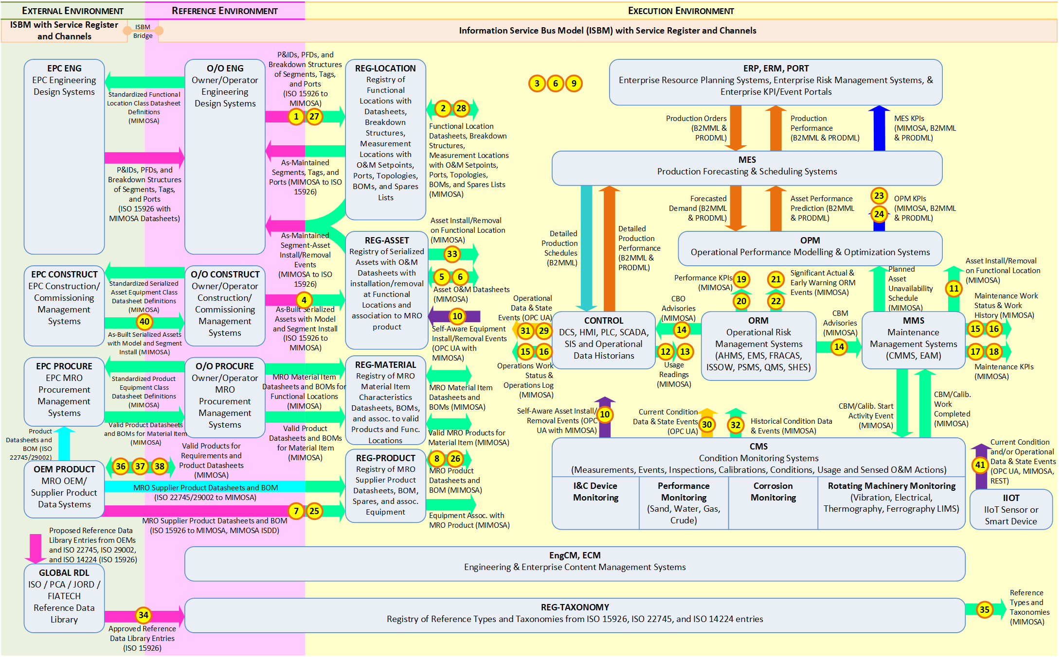
2. Identify CCOM data elements and BODs
Once a specific Use Case, Scenario and Event(s) are identified, the next step is to identify the specific data elements that need to be exchanged using which BOD(s).
Let us understand with the help of an example. Suppose the identified Use Case is Use Case 5 – “Asset Installation/Removal Updates” which describes the interactions between Operations (personnel) and Maintenance systems to perform a corrective maintenance task (removing an asset and installing a new asset) and the resulting publication of configuration updates (the asset removal/installation events) from the Maintenance Management Systems to Operations & Maintenance Systems.
The identified scenario is Scenario 11 – “Publish Asset Removal/Installation events from MMS to O&M” which specifies that the data content of the message exchange will contain functional location, asset, and time of the event (the data content requirements) and optionally the agent who performed installation/removal and the calendared maintenance work order associated with the installation or removal to provide the context. Scenarios also define the specific types of events (install and remove) from the MIMOSA reference data library, for example EventType having UUID: ecc99353-412b-4995-bd71-1cbc6fc16c7c represents “Installation of Asset on Segment” and EventType UUID: 3a45e126-b234-42a0-b3b1-07c29522d02d represents “Removal of Asset from Segment”.
This Scenario requires the sending/receipt of the Events – “Publish Asset-Segment Event Data” via the SyncAssetSegmentEvents BOD which describes the data required to update the asset configuration information through one or more CCOM AssetSegmentEvent objects (which associate an asset to a functional location at a specific time). Its requirements state that there is no expected response event and confirmation is optional (as it is intended to be a published event), and that the receiving systems must update their asset configuration information with the new association.
The Scenario and Event information tells us that the adaptor needs to be able create a SyncAssetSegmentEvents BOD, for which an XML schema is provided. The Event definition and related BOD schema references specific CCOM elements that need to be handled, chiefly:
- AssetSegmentEvent (required)
- Site (optional)
- Agent (optional)
- Manufacturer (optional)
- Model (optional)
- Asset (optional)
- Segment (optional)
While the BOD lists some of these as optional, it is important to look reference the definition of the elements and ensure any important elements are included. Typically, certain core elements need to be handled such as InfoSource. In the case of the required AssetSegmentEvent element, it includes:
- Asset
- Segment
- Agent
- CompletedWork
- EventType (inherited)
- EventLink (inherited)
Since the purpose of AssetSegmentEvent is to associate an Asset to a Segment, it is likely that a system publishing such events will need to be able to handle Asset and Segment elements. Moreover, the publishing system is not the System of Record for Assets nor Segments, so there would be no need to support the entirety of the Asset and Segment definitions, instead only the identifiers (UUIDs) of the Asset and Segment need be handles so that receiving systems can correctly associated the Asset and Functional Location internally by dereferencing the identifiers.
If the publishing system is a Work Management System, it is likely that the AssetSegmentEvent will be associated with a work item, so the CompletedWork element may need to be handled by the adaptor as well. The Scenario’s list of possible reference data types also gives an indication of what may need to be supported. In this case EventType is necessary and is listed in both the Scenario’s reference data types and an element of the AssetSegmentEvent itself. However, EventLink is unlikely to be required in this example, nor are Agent, Manufacturer, Model, and Site. Therefore, the analysis of CCOM data elements can be restricted to the following set of types:
- AssetSegmentEvent
- Asset
- Segment
- CompletedWork
- RequestForWork (referenced by CompletedWork to indicate which request has been completed)
- EventType, and
- InfoSource
Since there are many associations between elements in CCOM—taken all together they form an interconnected graph—it is important to carefully select the associations/nested XML elements that are handled by an adaptor to limit the scope of what needs to be implemented. The next step can also help limit the scope if analysis of the model and schema is not enough, as only the data that can be mapped from the system need be handled as CCOM data.
3. Map System Data to CCOM Elements
The system’s internal data schema needs to be inspected to determine what data is available, what it represents, and most importantly to what concepts and data elements of CCOM it is equivalent. This can be a difficult process but is essential in ensuring the correct information is being exchanged with other systems to arrive at a properly interoperable ecosystem. The previous step can help identify the relevant CCOM concepts and the analysis of the system’s schema may identify a slightly different set. The two stages can work together to identify the final set of data elements that are required to achieve the goals of the interaction (Scenario and Use Case).
When developing the mapping there are several factors to consider:
- Bi-directional vs. uni-directional mappings—uni-directional mappings may be simpler if all a system does is publish data but if it also receives requests it may be important that the mappings work in both cases
- Creation of intermediate entities—as there can be many differences between schemas, it is likely that the mappings will involve the creation of intermediate objects that need to be recorded somewhere (particularly in the case of bi-directional mappings); this may require an SDAIR or similar to register the mappings for use in future exchanges through the adaptor
- Reference data—some aspects of the internal schema may map to reference data types that are instances of the CCOM schema rather than elements of the CCOM schema itself; both need to be considered when performing mappings.
4. Identify required ISBM interfaces
The ISBM specification and service definitions files are available from the OpenO&M website. The ISBM is composed of a set of service interfaces to support various functionality such as configuration and management, request-response communication, publish-subscribe communication, and push notifications to client systems. The complete set of services is as follows:
- Channel Management Service: channel and security configuration
- Notification Service: allow notifications of new messages
- Provider Publication Service: publish messages
- Consumer Publication Service: read published messages
- Provider Request Service: read and respond to requests
- Consumer Request Service: send requests and read responses
- Configuration Discovery Service: provide service providers supported feature set
Different Scenarios typically require only a subset of services be implemented by a system; therefore, it is useful to reference the Scenarios in which your system is to participate to determine for which services clients must be implemented. In general, each Scenario will require one system to implement a Provider client (Publication or Request depending on modality) and one system to implement a Consumer client (Publication or Request to match the Provider modality). In addition, one or both systems may optionally implement the Notification Service to allow the system to be notified when a new message is received on a channel to which the adapter is subscribed. Finally, it is recommended that all systems implement the GetChannel operation of the Channel Management Service (and only that operation) to support the validation of channels before attempting to open a session, described in the following section.
4.1 Opening Sessions
To be able to post or receive messages on the ISBM, a system must open a session on the ISBM to receive a session identifier. It is assumed that the requisite channel and topic/s have already been created, and the ChannelURIs, TopicNames and AuthorizationTokens have been configured within the application.
The general pattern for opening a session on the ISBM is to first validate that the requisite channel and topic/s exist before opening the session. The figure below shows an example of the validation and open session pattern.
- The System will call GetChannel using a specified ChannelURI. If a ChannelFault is thrown or a required TopicName is not present, then the System can indicate as such and terminate.
- The System will call an open session method (i.e. OpenPublicationSession, OpenSubscriptionSession, OpenProviderRequestSession or OpenConsumerRequestSession) on the ISBM using the same ChannelURI as in the previous call. The returned session identifier will be subsequently used to post messages on or receive messages from the ISBM.
This general pattern of validating and opening sessions is recommended for all open session interactions.
For example, the Transform Engine will open subscription and publication sessions for receiving and posting messages. The number of subscriptions and publications will depend on the channel and topic design of the environment. Note: It is assumed that the Transform Engine is configured to forward messages from its subscription channels to the appropriate publication channels after message transformation. For systems communicating with the Transform Engine, the ChannelURI and TopicNames used to open publication and subscription sessions must correspond to those used by the Transform Engine. This will enable the Transform Engine to be a seamless component in the message pipeline.
It is recommended that topics follow the convention of describing the data type of the message content. This simplifies processing for consumers of the message when parsing the message content. While the ISBM supports a message being assigned multiple topics, because of the above recommendation, only a single topic should be assigned to a message. The Scenario descriptions include suggested Channel and Topic formats/names.
4.2 Closing Sessions
All systems must close sessions if no messages are expected to be posted or received on that session. The duration for expecting to post or receive messages depends on the environment design.
4.3 Session Lifetime Management
Publication, subscription, post request and post response sessions only need to be available for the duration of posting or receipt of a message/notification. However, to avoid repeatedly opening and closing sessions, a single session can be opened for the duration where messages are expected to be posted or received. The session can be persisted over hours, days or permanently depending on the scenario and ISBM implementation.
Note As publication messages are immediately expired once a publication session is closed, providers should not close sessions until they are satisfied that published messages have been read by consumers.
Note Persistence of sessions by the ISBM is not addressed in this document, as it is unique to the implementation.
Continuing with the example of Use Case 5, Scenario 11 — Once the physical work of installing the equipment has been undertaken and the maintenance management system is ready to publish an event, it must first format the data payload according to the SyncAssetSegmentEvent CCOM BOD. The structure is:
For sending SyncAssetSegmentEvent BOD, the Work Management System must implement a client for the ISBM Provider Publication and Channel Management (only the GetChannel operation) Services. While, the O&M Systems must implement a client for the ISBM Consumer Publication and Channel Management (only the GetChannel operation) Services. O&M Systems may implement the ISBM Notify Listener Service for message notification.
A channel should be created for removal/installation events for example – /Enterprise/Refinery A/Area A/Light Ends Area/ISO18435:D1.3. As outlined in the document ISBM Guidelines, topics should match the message content. Correspondingly, the topic format should be such as — OIIE:S11:V1.1/CCOM-XML:SyncAssetSegmentEvents:V1.0
5. Identify required infrastructure components
Once an organization has identified the Use Cases and Scenarios, the next step is to identify which infrastructure components of the OIIE ecosystem need to be used to achieve their objectives. The OIIE infrastructure components include:
- ISBM
- SDAIR
- Transform Engine
- CIR
- Service Directory
The Scenarios list which infrastructure components are required, including any configuration parameters and guidelines. In OIIE/PGI Pilot Phase 3.1, all in-scope Scenarios use the ISBM for message exchange and so include a suggested configuration for channels and topics; some Scenarios require, or may require, an SDAIR, and the Transform Engine occurs in the Scenarios for Information Handover as it is required to transform the ISO 15926-based Engineering data into CCOM-XML. The CIR and Service Directory will not be used in Phase 3.1 for simplicity of the infrastructure setup.
6. Build Adaptor
Once requirements have been identified, a design should be conducted that will address the system and user workflows, screen mockups, data models, test cases and other typical design artefacts used.
The benefit of the use of the ISBM specification is that it builds on top of basic Web Services to provide additional functionality including messaging patterns, routing, and security. It also provides an abstraction layer on top of middleware products to avoid coupling system integration to specific technology products. The additional specification by the OGI Pilot on defining common data exchange use cases and scenarios and the use of specific data formats and messaging patterns can then be used by system suppliers to build their adapters in an “ecosystem” approach.
To implement the adaptor, the Web-service definitions (SOAP/XML and/or REST/JSON) need to be obtained. The ISBM defines a minimal interface subset to Enterprise Service Buses (ESB) and other message exchange middleware, using a standard interface consisting of channels and topics. The benefit from this approach is to allow applications to expose a single, standardized interface rather than having to be custom built for every version and format of ESB or message exchange system.
The OpenO&M ISBM specification v1.0 was based on SOAP web services. The latest v2.0 specification supports plain HTTP/ JSON REST interface and is available here.
As indicated by the requirements and design, the actual development time required for the communications section of an ISBM module is fairly minor, particularly as most language frameworks have good support for WSDL and SOAP with code generation (e.g. Java has Axis2 and JAX-WS while .NET has WCF) and there are many code generators for OpenAPI targeting different languages. The majority of the time will be spent integrating the module with workflows and cross-cutting concerns such as error handling, logging and persistence.
Below is a list of software libraries that can be used by software vendors to support the inclusion of ISBM functionality in their products:
NOTE: These adapters have not yet been updated as per ISBM 2.0 specification.
7. Test Adaptor
While unit testing can always (and should always) be performed, integration testing is also invaluable. There are two options for integration testing: using an ISBM server developed by an external provider or developing a test ISBM server in-house.
To facilitate ISBM testing, the following tools can be used to publish to or receive messages from an ISBM server:
- Assetricity .NET ISBM Publisher – publish messages to an ISBM server
- Assetricity .NET ISBM Subscriber – subscribe to an ISBM server and save received messages to an XML file.
NOTE: These testing tools have not yet been updated as per ISBM 2.0 specification.