The sections below detail high priority handover requirements based on an OGI Pilot-prioritized set of information.
Reference Data Requirements
- Reference data should be ISO 15926 Part 2 compliant and semantically derived from JORD templates where possible.
- Reference data from ISO 15926 and PCA/JORD RDL should be used wherever possible for P&IDs and datasheets.
- This includes classification of plant items, properties, units of measure and enumerations.
- This requirement does not limit other reference data systems (e.g. Intergraph’s default library) being used in conjunction with ISO 15926 reference data.
- The order of preference for repositories is PCA/JORD RDL before third-party RDL.
- A link to the ISO 15926 reference data URI must be able to be unambiguously made from the data. This could be accomplished using a mapping document external to the data itself.
- Reference data should be standardized across all information packages to avoid multiple names for the same logical type/class. For example, the property types and unit of measure types for a P&ID and datasheet should be consistent.
- Classification of instruments in a P&ID should be at the more specialized level, e.g. FLOW CONTROLLER or FLOW TRANSMITTER, rather than a high-level classification level, e.g. PROCESS INSTRUMENT.
- Any customized symbols must be able to be exported to an ISO 15926 format Shape Catalogue using OWL templates or Proteus.
Metadata Requirements
- Metadata should be standardized across all information packages to avoid multiple definitions for comparable data objects. For example, date formats, significant digits and text field length should be consistently defined.
PFD and P&ID Requirements
- PFDs and P&IDs should be captured and stored in order to provide a logical plant topology that details functional locations and connections.
- The As-Designed and As-Built versions will be used for handover to O&M.
- The following content must be contained within a PFD/P&ID as structured data:
- Functional locations with primary key identifier, tag and type/classification (e.g. Horizontal Centrifugal Pump, Check Valve). Note The primary key identifier is expected not to change, even during tag renaming.
- Nozzles/ports on functional locations with type/classification (e.g. Inlet Nozzle, Signal Port)
- Connections/tie-ins between nozzles/ports
- Drawing/canvas dimensions
- X, Y coordinates for functional locations
- Symbol reference
- Symbol orientation
- The following content may be contained with a P&ID as structured data:
- Type/classification of connections (e.g. Mechanical Connection)
- The P&ID must be allocated to an item in the plant breakdown structure.
- Instruments in a P&ID should have separate controller/indicator, transmitter and element bubbles.
- Visually connected elements on a diagram must form a connected network for correct export of the logical topology.
- The topology can be considered as a graph with nodes and edges.
- A branch connector (e.g. pipe tee or tie-in) must be used when connecting together two piping network segments. Note Refer to Flow Representation section of the ISO 15926 P&ID model.
- An instrument connector must be used when connecting an instrument directly to a piping network segment. Note Refer to Flow Representation section of the ISO 15926 P&ID model.
- All temporary or soft-deleted items should be removed from the P&ID.
- P&IDs must be handed over in a native format that can be export to a ISO 15926 interoperable format (using OWL templates, XMpLant or Proteus), or in an ISO 15926 interoperable format itself. An image format, signed/stamped, is also permitted as long as it is accompanied by the aforementioned native and/or interoperable formats.
Tag/Functional Location, Make/Model and Serialized Asset Datasheet Requirements
- Tag/Functional Location datasheets should be captured and stored in order to provide parameterized requirements of functional locations.
- Model and Serialized Asset datasheets should be captured and stored in order to indicate parameterized capabilities of models and assets.
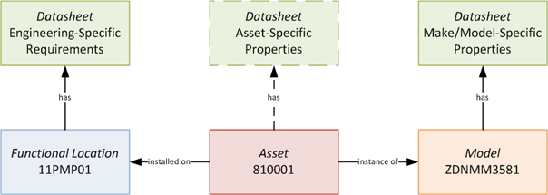
- A distinction should be maintained between the functional location datasheet, model datasheet and asset datasheet, as shown in the figure below, to avoid data redundancy and maintain data lineage/provenance. Note In the most common case, an asset datasheet will not exist; instead, the asset will inherit properties from the model datasheet.
- For each property on a datasheet, the following should be provided as separate fields:
- Property type (e.g. Upper Limit Pressure)
- Value (e.g. 1400)
- Unit of measure type (e.g. Kilopascal)
- Properties that have multiple values across multiple fields (e.g. minimum and maximum, upper and lower) should be analyzed to see if the values actually belong to different property types (e.g. Working Temperature with minimum and maximum fields split into Minimum Working Temperature and Maximum Working Temperature).
- This is to assist with export to interoperability standards and automated datasheet comparison.
- For each property type (e.g. Upper Limit Pressure), a value type (e.g. double) should be provided for parsing and validation purposes.
- Use ISO 8601 for the date format. If time is specified, then it must be accompanied by the time zone.
- If the value type of a property type is an enumeration, then a reference to the enumeration list as well as the complete list itself must be provided.
- Property types, unit of measure types, and value types should be standardized across all datasheets to (1) avoid multiple names for the same logical type and (2) automate the comparison between functional location requirements against model and asset capabilities.
- Datasheet sections (i.e. property groups) should be retained if present in the original data.
- Instrument and Control datasheet specifications should have the data that is specified in ISA-TR20.00.01-2007.
- Datasheets must be handed over in a native format that can be export to an interoperable format (ISO 15926 using OWL templates, MIMOSA CCOM XML or cfiXML) or in an interoperable format itself. An image format, signed/stamped, is also permitted as long as it is accompanied by the aforementioned native and/or interoperable formats.
Asset Installation Requirements
- Asset installation events should be captured and stored in order to identify the currently installed asset at each functional location. This information may be handed over via a Master Equipment List. Note See Section 2.1 in EPISTLE Process Industries Data Handover Guide – Part 2
- For each installation event, the following should be provided as structured data (separate fields):
- Functional location identifier or tag
- Asset identifier (e.g. serial number or other unique identifier)
- Date install completed (optional). Use ISO 8601 for the date format. If time is specified, then it must be accompanied by the time zone.
- Construction work order number reference (optional)
- Handover of information can either be delivered on a single event basis or on a batch event basis.
- Asset installations must be handed over in a native format that can be export to an interoperable format (ISO 15926 using OWL templates or MIMOSA CCOM XML) or in an interoperable format itself.